Bauman, Bruce Todd. “Prying Apart Semantics and Implementation: Generating XML Schemata directly from ontologically
sound conceptual models.” Presented at Balisage: The Markup Conference 2009, Montréal, Canada, August 11 - 14, 2009. In Proceedings of Balisage: The Markup Conference 2009. Balisage Series on Markup Technologies, vol. 3 (2009). https://doi.org/10.4242/BalisageVol3.Bauman01.
Balisage: The Markup Conference 2009 August 11 - 14, 2009
Balisage Paper: Prying Apart Semantics and Implementation
Generating XML Schemata directly from ontologically sound conceptual models
Mr. Bauman's first introduction to markup was in the early 1990's where he
oversaw the tagging of foreign language dictionaries in compliance with the Text
Encoding Initiative (TEI) standards and led a development team that produced
multi-lingual retrieval tool for those dictionaries based on the Standard
Generalized Markup Language (SGML) . Mr. Bauman became interested in using SGML
and then XML to solve entrenched interoperability problems. This led him to look
seriously at information / data modeling and now ontology for answers to
interoperabilities' persistent questions. Twelve years later he has yet to solve
those entrenched problems (this is really hard).
Mr. Bauman has been attending [off and on] the Balisage series of conferences
since the HyTime days, and has watched XML grow up over its 11 year history.
Mr. Bauman holds a BS in Computer Engineering and an MS in Computer
Science.
Central to interoperability is a shared conceptualization of the domain or
universe of discourse (UoD). A conceptual model (CM) documents this shared
understanding between people in a formal language, augmenting prose but neutral of
later implementation decisions. Having such an explicit layer has benefits for
enhanced interoperability, higher quality implementations, reuse and mapping, and
as
such is recognized as desirable by many modeling frameworks. In this paper, we
describe our motivation and efforts to date, to use the ontologically well founded
profile of the Unified Modeling Language (UML) proposed in Guizzardi-2005 to create such models. Relevant subsets of a CM form
the basis for physical data models (PDM) targeting specific technologies, in this
case the generation of Extensible Markup Language (XML) schemata represented in the
World Wide Web Consortium (W3C) Schema Language (XSD). These physical data models
are annotated by a developer, with a set of encoding directives. These encoding
directives and the custom developed software that interprets them to map concepts
in
the CM to their expression in an XSD, are our principle contribution. The CM
language, the XSD encoding annotations, and the software are briefly
described.
Schemata in the World Wide Web Consortium's (W3C) Extensible Markup Language (XML)
Schema language (XSD), Relax Next Generation (RNG), Structured Query Language (SQL)
Data
Definition Language (DDL), Resource Description Framework Schema (RDFS), or Web Ontology
Language (OWL)) are typically created directly. A basic text editor can be used,
although more likely today it will be with a design tool that uses visual symbols
with a
more or less bijective mapping to the constructs in the chosen implementation language.
Various profiles of the Unified Modeling Language (UML) class diagrams have been
proposed as a visualization for XSD design Bernauer-2004; various forms
of Entity Relationship Diagrams (ERD)'s are the preferred choice for relational database
(SQL DDL) design. And then there are the numerous languages specific to a given vendors
tool.
As useful as these visual design languages are, they are first, representations of
a
design in a specific implementation language, and only secondarily do they reflect
the
semantics of a Universe of Discourse (UoD) or domain.[1] Or as stated in the introduction to Guizzardi-2005 pages 7
- 8.
Nowadays, many languages exist that are used for the purpose of creating
representations of real-world conceptualizations. These languages are sometimes
named domain modeling languages (e.g., LINGO), ontology representation languages
(e.g., OWL), semantic data modeling languages (e.g., ER), among other terms. ...
Although these languages are employed in practice for conceptual modeling, they
are not designed with the specific purpose of being truthful to reality. For
instance, LINGO (Falbo & Menezes & Rocha, 1998; Falbo & Guizzardi
& Duarte, 2002) was designed with the specific objective of achieving a
positive trade-off between expression power of the language and the ability to
facilitate bridging the gap between the conceptual and implementation levels.
This preoccupation also seems to be present in Peter Chen's original proposal
for ER diagrams (Chen, 1976). OWL (Horrocks & Patel-Schneider & van
Harmelen, 2003) has been designed with the main purpose of achieving
computational efficiency in an automatic reasoning process. Some other
languages, such as Z (Spivey, 1988) and CC Technique (Dijkman & Ferreira
Pires & Joosten, 2001), take advantage of the simplicity of the well-defined
mathematical framework of set theory. Finally, some of the languages used
nowadays for conceptual modeling were created for different purposes, the most
notorious example being the UML (OMG, 2003c), which initially focused on
software design.
Designs reflect hard engineering trade-offs, starting with the initial
choice of an implementation language which will have only limited abilities to express
the full richness of the UoD, and ending with the numerous design choices made (e.g.,
denormalization, implementing relationships, by reference, vs. by value, collapsing
generalization hierarchies). This intertwining of implementation design and semantics
with semantics taking a back seat, means that no formal model representing just the
semantics remains. The sole guardian of pure semantics is the informal prose, in the
text box labeled Description.
The use of prose to capture semantics is of course essential, the target audience
that
needs to fully account for semantics are people, and natural language with all its
richness, complexity, and nuance is essential. The challenge of course with relying
only
on words is their ambiguity. Although formally the interplay of words with meaning
is
studied in fields such as linguistics, semiotics, phenomenology, communication theory
etc., Humpty Dumpty sums up the problem rather well.
When I use a word, Humpty Dumpty said, in a rather scornful
tone, it means just what I choose it to mean, neither more nor less.The question is, said Alice, whether you can make words
mean so many different things.The question is, said Humpty Dumpty, which is to be master - that's all. Alice was too much puzzled to say anything; so after a minute Humpty Dumpty began
again.
They've a temper, some of them - particularly verbs: they're the
proudest - adjectives you can do anything with, but not verbs - however, I
can manage the whole lot of them! Impenetrability! that's what I say!
Lewis Carroll, Through the Looking
Glass
The lack of a separate design neutral, but formal accounting of semantics has several
drawbacks. The first, is that ultimately for two or more systems to interoperate they
must share a compatible understanding of the UoD, they needn't necessarily share the
same design. This task of determining, and ultimately documenting via a mapping,
compatibility, or recognizing when and where it is not possible is made more difficult.
Second, when people negotiate to decide on a common language for sharing information,
the discussion can / will often stray between discussing differences in meaning, and
differences in design. Its helpful in resolving disagreements to know which of the
two
classes of discussion one is having. Third, it is perfectly reasonable, desirable,
and
necessary to implement the same UoD in multiple implementation languages and/or in
multiple designs. Capturing explicitly a model of the UoD allows it to be reused.
This
is even more beneficial if the domain is highly complex and/or technical and modeling
it
correctly is expensive, time consuming and difficult.
A solution, is to create a conceptual model (CM). A model that formally represent
those aspects of the UoD that are deemed relevant for a particular purpose, (e.g.,
the
static structural aspects of a domain essential to the development of information
models), but that is neutral of physical design decisions. Then from that model produce
though a semi-automated mapping process logical / physical level models, from which,
because of their isomorphism to a targeted schema language, a schema can be
automatically produced.
The idea is hardly new.The issue is essentially one of implementation
independence - the goal (or assumption) that the conceptual data model be
independent of the implementation language. This view dates at least from Chen
(1976), is the basis of the conceptualization principle in the ANSI/SPARC
framework ISO-TR9007, and has been frequently re-stated ...
This ideal does not appear to be achieved in practice (Simsion-2007, p. 51). Nor is the idea unique to the data modeling
community from which the above quote originates. The Model Driven Architecture (MDA)
of
the Object Management Group (OMG) has the concepts of the Platform Independent Model
(PIM) and Platform Specific Model (PSM) OMG-MDA. The recognition of the
need for conceptual models to back up XML schema design is also old, dating back to
the
beginning of XML, and XML's predecessor, Standardized Generalized Markup language
(SGML).[2]
The proposal outlined in the sections that follow is also in one sense nothing new.
Its strength is not in the idea that a conceptual model is useful, but in what modeling
language has been pressed into service. The conceptual modeling language outlined
below,
is a subset of that proposed by Giancarlo Guizzardi, principally in Guizzardi-2005 . In his 2005 work, a foundational ontology in later
works referred to as the Unified Foundational Ontology (UFO), designed to capture
agreements about the semantics of a UoD by people and for people, visualized using
a
profile of UML 2.0 is defined. We have changed, only trivially his proposal based
on
some ideas from data modeling Simsion-2005 and other sources both to
simplify the language, and make it more familiar to people with a data modeling
background. The UFO builds upon cross disciplinary knowledge as well as research in
formal ontology [as applied to computer science] that has occurred in the last fifteen
years.
From a conceptual model based on this language, multiple physical data models (PDM)
which subset, and / or extend, the larger conceptual model are generated. A PDM is
then
annotated by a designer with a set of encoding options that specify how the concepts
in
the CM should be represented in the XSD. We have chosen the initial set of encoding
options based on internal experience with creating UML to XML schema mappings since
2000-2001 much like those surveyed in Bernauer-2004. Software written
in Extensible Stylesheet Transformations (XSLT) version 2.0 is the primary mechanism
by
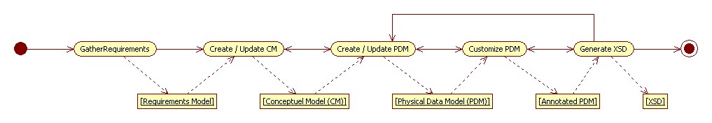
which the annotated physical data models are compiled into XML schemata. Figure 1 show an overview of the complete process.
Figure 1: Model Development Process
In the following sections, our requirements for a CM modeling language are explained,
followed by a brief outline of the ontologically well founded language we have selected.
This is followed by an example physical data model, that has been annotated with XSD
encoding directives. How those directives drive the compilation of that PDM into an
XSD
is explained. The software implementation in Sybase Power Designer (a commercial data
modeling / enterprise architecture tool), and in particular the implementation of
the
XSLT code that generates an XML schema from it, is touched on briefly. This is followed
by a section on further work, and conclusions. Appendix A contains a more complete
account of the XSD encoding options available.
Semantics
An Ontologically based Conceptual Modeling Language
All models are wrong, some are useful. George Box
This frequently repeated quote represents a very pragmatic definition of what makes
a
good model and it is the position adopted here for both models, and by extension
modeling languages and the meta-models / ontologies that they are based on. As such,
no
claims are made that the modeling language briefly introduced below, the foundational
ontology it is based on, or the models that are described with it, have any lock on
a
single, absolute truth. Instead, the language has been chosen / customized because
we
believe it can meet the following pragmatic requirements[3]:
Modeling Language Requirements
Document an agreement between people, to a reasonable level of
specificity,[4] those aspects of a UoD or domain that are relevant for the
design of information/data models, but without committing to a specific
implementation language.
Support through human directed action, and to the greatest extent
possible, the automatic generation of designs and schemata encoded as XSDs
appropriate for information exchange .
Similarly support the generation of designs and schemata encoded as SQL
DDL appropriate for relational data bases.[5]
If possible, support the generation of designs and schemata encoded in OWL
Description Logic (DL).[6]
Be reasonably approachable by personnel trained in traditional logical
data modeling using ERD notations.[7]
Reduce the level of construct variability, to support the development of
models in a distributed environment.[8]
Accommodate both vertical and horizontal variability, to support the
integration of multiple different perspectives of the same concept within an
enterprise.[9]
After attempting to adapt unsuccessfully both standard UML and ERD notations to meet
the above requirements, the realization through both experience and subsequent
examination of the literature (e.g., Simsion-2007 ), was that both
languages, and the informal ontologies that they are based on, were too biased for
design in a specific technology. This led us to examine how formal ontology[10] could be employed, not in the computer science sense of producing a specific
artifact, expressed typically in a formal logic variant, but in the philosophical
sense.
... Formal Ontology deals with formal ontological structures (e.g., theory of
parts, theory of wholes, types and instantiation, identity, dependence, unity),
i.e., with formal aspects of objects irrespective of their particular nature.
The unfolding of Formal Ontology as a philosophical discipline aims at
developing a system of general categories and their ties, which can be used in
the development of scientific theories and domain-specific common sense theories
of reality (Guizzardi-2005, p. 5).
In the end we settled on the formal foundational ontology, and its representation
in
UML defined in Guizzardi's 2005 PhD thesis Guizzardi-2005 and
subsequent research papers Guizzardi-2006aGuizzardi-2006bGuizzardi-2007Guizzardi-2008 to name just a few, that define the Unified
Foundational Ontology (UFO). Some small changes in terminology were made to make the
UFO
more approachable to classically trained ERD modelers. Its also important to point
out
that no claim is being made that the UFO is the only upper level ontology that will
meet
the requirements outlined above. What is being claimed is that the selection and
explicit recognition of a formal upper level ontology as the basis for domain ontologies
/ models is essential to give those models the precise semantic underpinning needed
to
enable interoperability. What follows is a necessarily brief introduction to UFO and
its
representation in UML.
This ontology / language is used to facilitate communication between people, although
admittedly it is not something that a person, without training will fully grasp.
[The ontology ] aims at capturing the ontological distinctions underlying
human cognition and common sense.Guizzardi-2005 The
ontology is the basis for recording one, (among many possible) conceptualizations
of the
real-world, defining what is a valid state of that world. As such, the language symbols
designate real-world objects, and not information structures as is the case is the
PDMs
derived from it. Optionality on attributes and relationships is strongly
discouraged[11], ... from an ontological standpoint, there is no such a thing as an
optional property and, hence, the representation of optional cardinality leads to
unsound models (in the technical sense of chapter 2), with undesirable consequences
in terms of clarity (Guizzardi-2005, p. 139).
Endurant Types
Like many upper level 'common sense' ontologies the first level distinction is
between endurants and events, or things that exist in time, and
maintain their identity, and things that exist of time. Unlike
in the UFO, and in particular UFO-B, in our subset the concept of an event is not
further specialized. Endurants are. Endurants (e.g., kind, category, role,
associative) are specialized based on three basic criteria:
Existential independence: Is the concept existentially independent,
dependent on exactly one other concept, or dependent on two or more
other concepts? Existentially dependent concepts, are those that if they
are not seen in, or inhered in another object, don't exist.
Single principle of identity: Does the concept convey a unified
principle of identity? (e.g, all instances of the type have a common way
in which they are identified; and thus, instances can be counted
directly).
Rigidity: Is each instance of a type always of that type? (i.e., the
instance - type relationship is rigid), or is it only sometimes
(typically within some period of time), associated with a type (i.e.
anti-rigid)?
This leads to the following breakdown:
Table I
Endurant Types
Name
Independent
Identity
Rigid
Description
kind
+
+
+
A «kind» represents a substance sortal whose instances are
functional complexes. Examples include instances of Natural
Kinds (such as Person, Dog, Tree) and of artifacts (Chair, Car,
Television). (Guizzardi-2005, p.
317)
role
+
+
-
A «role» represents a phased-sortal role, i.e. anti-rigid and
relationally dependent universal. For instance, the role student
is played by an instance of the kind Person. (Guizzardi-2005, p. 319)
category
+
-
+
A «category» represents a rigid and relationally independent
mixin, i.e., a dispersive universal that aggregates essential
properties which are common to different substance sortals. For
example, the category RationalEntity as a generalization of
Person and IntelligentAgent. (Guizzardi-2005, p. 319)
role category
+
-
-
A «role category» represents an anti-rigid and externally
dependent nonsortal, i.e., a dispersive universal that
aggregates properties which are common to different roles. In
includes formal roles such as whole and part, and initiator and
responder. (Guizzardi-2005, p. 320)
Examples include resource, asset, communicant.
dependent
- (1)
+
+
A <dependent» universal is an intrinsic moment universal.
Every instance of dependent universal is existentially dependent
of exactly one entity. Examples include skills, thoughts,
beliefs, intentions, symptoms, private goals. (Guizzardi-2005, p. 335)
associative
- (2 or more)
+
+
Every instance of an <<associative>> universal is
existentially dependent of at least two distinct entities.
Associative's are the instantiation of relational properties
such as marriages, kisses, handshakes, commitments, and
purchases. (Guizzardi-2005, p.
335)
Attributes and Datatypes.
[Model] attributes are used exclusively to represent simple existentially
dependent concepts such as height, weight, color, a social security number, that can
be mapped directly to single or multi-dimensional value spaces as represented by
data types.[12]
Our treatment of datatypes doesn't vary from that found in xsd:schema and other
languages and so is not elaborated on here. A discussion on the ontological
foundations of data types as they relate to quality structures, and quale can be
found in Guizzardi-2006a or the work it is based on
Gärdenfors, P. "Conceptual Spaces: the Geometry of Thought", MIT
Press, Cambridge, USA, 2000.
Table II
Data Types
Datatype
Description
primitive
The value space defined by a set of built in data types. (e.g.,
string, float, integer, octets, boolean, data time, date,
time).
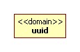
domain
A value space based on a primitive type constrained by range /
length / pattern restrictions.
enum
A value space based on a primitive type constrained by enumerating
its possible values.
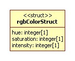
struct
A multidimensional value space (e.g., color as hue, saturation,
intensity).
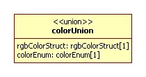
union
A value space formed by the union of 2 or more other data
types.
Association
The representation of associations is the one part of the meta-model that deviates
somewhat from that defined in Guizzardi-2005. Guizzardi specifies
a number of association types, often specific to the pairs of endurant types being
related. The position taken here is that a simpler characterization that collapses
many of the UFO association types into the three types of identifying,
non-identifying, and aggregation/composition (whole-part) is sufficient. Identifying
and non-identifying relations are an important distinction made in ERD modeling,
between those associations linking entities with a shared identity, and those that
are not. The concepts that do not have independent existence (e.g., dependent,
associative) must be tied through identifying relations to concepts that do, and can
thus provide identity to them. Concepts that are independent are tied together with
non-identifying relations.
A special form of non-identifying relation is the whole-part (meronymic) relation.
Like UFO, and UML, we define the relationships of aggregation, and composition, and
adopt UFO's semantics to clarify the ambiguous treatment of them in UML.[13]. Specifically we have adopted the following additional constraints that
are defined in UFO.
Table III
Whole - Part Instance Constraints
Name
Description
Note
Example
shareable
Indicates whether an instance of a part can locally be shared by
more then one instance of a whole.
Shareable is represented as UML aggregation (i.e. an open diamond on
the whole side of the association). Non-sharable is represented as
UML composition (e.g., a closed diamond on the whole side of the
association).
The whole / part relationship between a research group and a
researcher is locally sharable, meaning that an instance of a
researcher can belong to more then one research group.
inseparable
Indicates that the instance of the part is dependent on the instance
of a whole (i.e. if the instance of the part is removed from the
instance of its whole, it ceases to exist).
Represented with the UML constraint {inseparable} on the
association.
The relation between a human body and its brain is inseparable
(assuming the nonexistence of brain transplants), meaning that if a
brain is separated from a body, it ceases to exist.
essential
Indicates that the instance of the whole is dependent on the
instance of the part (i.e. if the instance of the part is removed
form the instance of its whole, the whole ceases to exist.)
Represented with the UML constraint {essential} on the
association.
The relation between a human body and its brain is essential,
meaning that if a brain is separated from a body, the body ceases to
exist.
Generalization
Generalization relations are supported between classes, associations, and
attributes. Generalization between concepts that have a single principle of
identity, the so called sortals (e.g., kind, role, dependent, associative), and
those that do not, the so called non-sortals or mixin (e.g., category, role
category) is treated differently. A concept with identity can only get that identity
from a single source, and thus only single inheritance is allowed in this context.
Multiple inheritance is supported between the non-sortals, or between the sortals
and non-sortals. A solid generalization line (UML generalization) is used for
generalization between sortals and sortals and between non-sortals and non-sortals.
A dashed line (UML realization) represents the generalization relation between a
sortal 'realization' of a non-sortal.
The presence of constructs such as the non-sortals, and the fact that the sortals,
can use multiple inheritance to relate to them, supports the representation of
multiple overlapping categorization schemes necessary to reconcile horizontal
variability. The broad support of generalization between all model concepts (e.g.,
attributes and associations) supports the need for vertical variability.
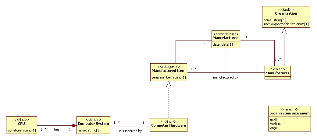
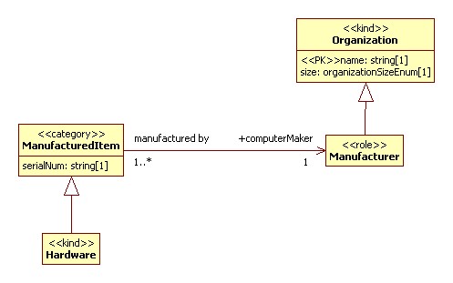
Example
The simple model example below demonstrates some of the model constructs described
above, and will be used as the source for describing the XML encoding options below.
Figure 2: Sample Model
Conclusion
There are numerous other constraints implemented in
UFO and its expression in UML that are not touched upon here. For example the
pattern for explicitly dealing with <<role>> brings uniformity to the
expression of a very common concept, that is only informally dealt with in common
modeling languages like UML and ERD. As another example an anti-rigid type cannot
be
a supertype to a rigid type. These rules together create restrictions on how
concepts can be related to each other, reducing the likelihood that skilled modelers
will produce unsound models, and increasing the likelihood that they will use model
constructs in similar ways (i.e. construct variability will be reduced). These
additional constraints unfortunately do not make the creation of good models any
less challenging intellectually, a challenge that will be brought up again later in
the conclusion.
Design
XML Schema Encoding Annotations
The design phase that ends with the ability to automatically generate an XSD starts
by
creating a copy of some subset of the larger conceptual model. During this generation
phase the target implementation language is selected, in this case the target language
is a W3C XML schema. This subset copy, called a physical data model (PDM) is then
modified in two ways. First, additional diagrams may be added to tell a story customized
to specific perspective that a customer has over a UoD. Second, the physical model
is
changed. Anything can be changed including the addition or deletion of modeling
constructs as needed. The more common changes include renaming concepts to reflect
preferences by a customer.[14], selecting which attributes will function as keys, changing the navigability
on associations, and the selection of specific XSD encoding options.
Both properties defined by UML 2.0 (e.g., association end navigability) and additional
properties added as extensions to base UML are used. Some model properties apply
globally to the entire model, and thus affect the entire XSD being generated (e.g.,
the
namespace of the XSD), others apply to the encoding of a specific modeling construct
(e.g., class, attribute). In some cases the same property can appear both globally
and
locally. If so, precedence is given to the local value. Most encoding options have
default values (e.g., [UML] attributes get encoded as xsd:element). If an encoding
style
is being used see Appendix A, whole sets of encoding options plus
built in logic that keys off of the semantic constructs in the model get enabled.
Thus a
default XSD can be produced with minimal effort. Yet fine grained control can also
be
exercised by setting individual encoding properties if desired.
A complete enumeration and explanation of all of the available encoding options is
beyond the current scope. A brief summary of the most common options is contained
in
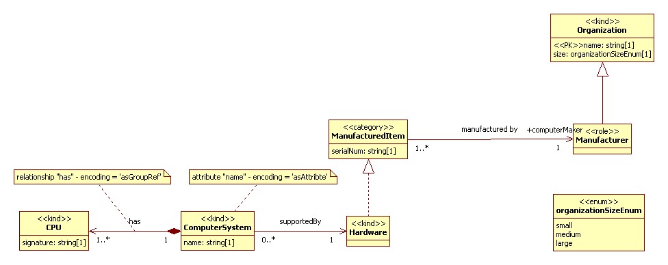
Appendix A. Below, a subset of the example model introduced above
is used to explain how one set of encoding options produces an XSD.
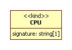
<<kind>> CPU is created as an
xsd:group. By default an xsd:complexType
is generated for all of the sortal types, but because an inbound
association has explicitly been set to encode 'asGroupRef', a group is
created. Encoding of classes is driven by defaults for its particular
type (e.g., <<kind>>, <<category>>) and /or by the schema
structures necessary to honor the needs of inbound relationships. This
means that any single class could cause the generation of
xsd:complexType, xsd:group and
xsd:attributeGroup structures.
Attribute signature is created as an
xsd:element within the xsd:group. By
default [UML] attributes get represented as xsd:element.
The name created for the element is "CPUSignature" based on the default
setting for a global default that controls the name syntax applied to
the creation of XML elements. In this case because of the group
reference, a name is chosen that appends the class name to the attribute
name so as to not lose needed context when the created XML element is
referenced from 'ComputerSystem'.
<<kind>> ComputerSystem is created as an
xsd:complexType, and as a global
xsd:element declaration. The UML visibility property on
a class controls whether a global complex type and element (visibility =
'public'), a global element with an anonymous complex type (visibility =
'protected'), or just a complex type (visibility = 'private') is
created.
Attribute name is encoded as an
xsd:attribute based on the encoding="asAttribute"
setting attached to it.
An xsd:group ref="" with a maxOccurs set to
unbounded to the group CPU is
created based on the encoding option set for the navigable outbound
relation to it.
Finally an xsd:element reference is created to represent
the outbound relation to Hardware. The
xsd:element reference construct is used for two
reasons. Broadly, the encoding of relationships takes two forms, by
value, and by reference, with multiple by reference styles to choose
from. By reference encodings require keys (one or more attributes whose
values can be uniquely used to identify a single instance of the
targeted class) to reference the construct. Because no keys are
available a by value encoding is used. Because the visibility property
of Hardware is public, a xsd:element
ref="" is used.
<<kind>> Hardware is created as a global
xsd:complexType and xsd:element.
An xsd:group ref="" is created to represent the
realization relationship to ManuracturedItem. An
xsd:group reference is used because the default
encoding for ManufacturedItem as a
<<category>> is xsd:group.
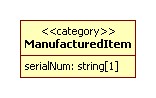
<<category>> ManufactureredItem is by
default encoded as an xsd:group. The mixin / non-sortal
class types of <<category>> and <<role category>> can be
used to cross-categorize the sortal class types. As such its quite
possible that a sortal will have generalization relations (represented
as UML realization visually) to many of them; effectively allowing for
multiple inheritance. Because of this group / group referencing is used
by default.
Attribute serialNum is created as an xsd:element
by default.
The outbound association manufacturedBy gets
encoded as an xsd:element called Manufacturer with a
datatype of string and whose value represents the key of the class
Organization. The key of
Organization is the [UML] attribute
name as indicated by the <<PK>>
stereotype. The reason this construct is created to represent the
relationship manufacturedBy is as follows: By a
settable default, associations to classes that have available keys use
those key(s) to implement a relationship by reference. If there is only
a single key, the name of the class being pointed at is used to name the
relationship.
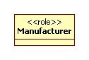
<<role>> Manufacturer is by default encoded
as a global xsd:complexType and xsd:element.
Because it has a generalization relation to another sortal type, and
there can be only once such generalization relation present per the
modeling language constraints, complex type extension can safely be used
to implement it. Because the default setting is to generate substitution
groups, one is created for Manufacturer and
Organization.
<<kind>> Organization is by default encoded
as a global xsd:complexType and
xsd:element.
Attribute name is by default encoded as an
xsd:element.
Conclusion
By no means does the set of encoding options available exercise every last corner
of the W3C XML schema specification, but they do allow, especially when used in
combination, for a surprising variability in encoding choices. New options are added
as they are needed, and thus far, elegant solutions to generate a given encoding
choice have always been possible without requiring that the models be changed in any
way other than with the addition of new encoding annotations. In essence the
implementation level decisions are effectively segregated and do not perturb the
semantic representation.
Software
The creation and maintenance of multiple layers of models and the subsequent
generation of XSDs would not be feasible without the correct tooling. The modeling
tool
we use is Sybase Power Designer; a market leading tool in traditional [relational]
data
modeling. It was selected for a variety of reasons, not the least of which is its
extensive ability to be customized, and ability to generate / merge / compare / track
the relations between multiple models. It has been customized to support and enforce
the
rules of the conceptual modeling language outlined above. This has involved extending
the meta-model that underlies Power Designer with additional [extended] properties,
modifying the forms displayed under certain menus, and writing additional trigger
code
to enforce the rules of the conceptual modeling language (e.g., section “Conclusion”). The code that create the XSD has been implemented
outside of Power Designer to avoid coupling it to a particular vendor's product.
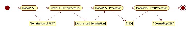
The architecture for this XSD complier, called unimaginatively
Model2XSD is shown below Figure 6. A
relatively simple routine written inside Power Designer in visual basic script
serializes the model as XML based on a custom designed markup language.[15] An XSLT 2.0 pipeline is then called to compile the XML into an XSD. The XSLT
program consists of several processing stages and supporting libraries of functions
and
configuration files. The Model2XSD-Preprocessor is used to add
additional constructs to the serialized model file if needed based on selected encoding
options. The Model2XSD-Processor creates the XSD. Finally the
Model2XSD-Postprocessor, optionally, does certain XSD clean-up
activities that can simplify the resultant schema.[16] All of these pieces of code are backed up by two function libraries,
Model-Utility primarily contains functions that navigate the physical
model as represented in XML (e.g., getting a concept's supertype, all its subtypes,
etc.). This library does not contain any functions specific to the generation of an
XSD
and thus could be reused in other generation tasks.Model2XSD-Utility"
contains functions specific to the generation of XSD files.
Figure 6: Model2XSD Process Flow
Further Work
Our application of the techniques outlined above is in its infancy. As we continue
to
gain experience, refinements in both the conceptual modeling language, the encoding
rules for XSD, and the software support for all of the above are inevitable. It is
possible that we will see the benefit of adopting more of the UFO, or possibly less.
As
we develop more XSDs we will undoubtedly have requirements for incrementally adding
to
our tool box of encoding annotations. It is a testament to the strength of the
conceptual modeling language that thus far we have been able to algorithmically generate
any necessary encoding we need.
In roughly priority order these are the current areas of interest we are
pursuing:
The processes and tooling needed to support the maintenance, change
management, and synchronization between a set of related models (conceptual,
physical,) and schemata (XSD) that are expected to evolve on independent time
lines, with differing constraints (e.g., the physical models and resultant XSD
files will be subject to pressures to maintain backwards and/or forward
compatibility for some period of time) and likely to be changed by independent
groups.
Work on how the physical data models are visually represented. As these models
are based on the conceptual model, but lead to an XSD, a tension naturally
arises as to how they should be visualized. Should the visualization reflect its
semantic roots in the CM, or the structure of the resultant XSD? And how do all
of the XSD specific encoding directives get represented visually? Currently many
are not, which makes it needlessly difficult to make the leap from model to XSD.
Our hope is that we can keep the physical data model visualization more closely
aligned with its conceptual roots, and through graphical overlays show the XSD
encoding annotations, but this remains to be seen.
Create code that automatically adds documentation into the generated XSDs that
reflect semantic distinctions present in the conceptual model that are
intentionally excluded from the resultant XSD. This occurs, for example, when an
XSD is generated that has collapsed what are multiple subclasses in the CM into
a superclass. All of the attributes and relations present in the sub-classes
become optional in the super. It's not that there is a fundamental change in the
conceptualization of the domain when this is done, it's much more likely that
the enforcement of a set of constraints is being moved from the schema to
software. It should be possible to generate additional documentation and embed
it into the XSD to make note of these relevant rules.
Prototype the software needed to generate other implementations (e.g., DDL,
OWL).
Explore whether, when different physical designs all originating from
overlapping parts of the same conceptual model are created, it is possible to at
least partially automatically create the needed XSLT code that would be required
to translate between them.
Conclusion
The adoption of a multi-layered model development process consisting of one (or a
small number of) conceptual models as the basis for potentially many physical
implementation models; the selection / customization of the UFO visually represented
as
UML class diagrams, as a conceptual modeling language; the design of rules for compiling
these models into an XSD; and the implementation of all of the above using Sybase
Power
Designer and XSLT is all still relatively new. We have only recently started exercising
this methodology fully to deliver products (XSDs) to internal customers. We are still
learning, and further customizing our techniques and their implementation in software.
So far our experience with using these techniques is anecdotal. It is both sobering
and
promising...
Challenges
... the short story is that good design involves hard thinking. And that
means it’s just hardSperberg-McQueen-2008. Although the quantification of what is
good design, is an interesting challenge in and of itself, it is
indeed very hard, both to do, and often to justify taking the time to do. On the one
hand the conceptual modeling language outlined above, with its more restrictive
rules can aid a good modeler in coming up with better, more sound models. The whole
methodology with its emphasis on semantics can lead to higher quality XSDs, at least
in the sense that they are semantically well grounded. But the bar for creating good
models is still high if not higher. To create a truly good design all the way from
creating a conceptual model to creating a good physical design takes quite a rare
skill set. Design activities require distinct skills - and arguably certain
personal characteristics. (Simsion-2007, p. 8)
Detailed knowledge of the domain being modeled, detailed knowledge about how best
to
conceptualize a domain, in particular knowing what level of abstraction to use, and
recognizing how to separate out, and deal with some of the orthogonal concerns that
creep in[17], how to effectively represent and communicate that conceptualization in
a modeling language, and how best to represent it in a chosen technology are all
needed. Of course these skills can be split across several individuals, but that
splitting leads to its own challenges. Finding, or training people to do this work
well is difficult Data modeling is notoriously difficult to learn and
teach. (Simsion-2007 , p.8)
And then there is the problem of finding the time to do this work. It is hoped
that the techniques outlined above, specifically meeting requirements 1 and 2 will lead to
greater reuse possibilities, and thus allow for the quick repackaging of already
done hard work. None the less, creating high quality, semantically well-founded
designs takes time, and time is a precious resource in many projects, whose use must
be justified.
Any group of systems that are information focused, and need to share that
information either through exchange or a shared data store, get coupled to the
information designs that underpin them. If these systems need to have a deep
understanding of the semantics behind the information (i.e., software is directly
creating, modifying, taking action on what the information means vs. just storing
/
presenting it and leaving the heavy semantic lifting to people), the coupling is
tight, and changing the information design very expensive. So too is creating a deep
semantic mapping between different, typically underspecified designs, or conversely
recognizing that they can't be mapped. This expense leads to the conclusion that in
many cases the up-front investment in good design is well worth it.
Finally there is the lack of adequate tool support. We have taken an industry
leading data modeling tool and augmented it to support ontology development leading
to an XML schema. It has required a reasonable amount of customization. Even with
these customizations there are many things that we would like the tool to do that
it
can't. Nor are we aware of any tool that has the full feature set we need to truly
create and maintain requirements models mapped to implementation neutral conceptual
models coupled with implementation specific design models from which XSD, DDL, and
OWL can be generated, and to do so on a large enterprise wide scale.
The selected modeling language is helping our internal team
communicate and reach agreement on conceptualisations of the UoD(1. It is also helping us to clarify our
prose descriptions of a UoD. Unlink ERD and UML in practice, where the
visualization reflects the implementation, conceptual models based on
UFO reflect the semantics, and these semantics should be mirrored in the
prose.[18] On many occasions we have created model concepts, then
written their prose definitions and found that the model and the prose
contradict each other. When this happens this points to a fundamental
problem and either the prose or the model has to be changed.
The semantic richness, precision, and design neutrality of the
conceptual modeling language, coupled with the flexibility of the XSD
encoding rules, and the fact that implementation models are kept
distinct from, but tied to, the conceptual model grant great flexibility
in creating XSDs well tailored to a customers need 2. This flexibility has been exercised twice,
when our team was tasked with creating a conceptual model reverse
engineered[19] from existing format specifications and then
forward-engineer back to a new XSD with very specific encoding
constraints.
Support of using the same conceptual models to support designs in
other implementation languages 3, 4, is promising, but unproven at this point. If it
were proven it would both re-enforce that the conceptual modeling
language is indeed largely independent of implementation design biases,
and add to the business case of investing in the development of models
that could be more widely reused.
Early evidence does support the claim that construct variability 6 is reduced, primarily in the use of
attributes, and for representing roles.
Likewise, early experience is that the conceptual modeling language is
better at documenting horizontal and vertical variability 7 and representing how different
choices relate to one another. Representing this variability in the same
conceptual model, however does complicate the resulting models and their
presentation visually.
An additional benefit that was not directly sought is that the code
that generates the XSD files partially mitigates the need for the
modelers using it to fully grasp all of syntactic and grammatical
nuances of the XSD language.
Appendix A. Physical Encoding Options
This section describes some of the more commonly used encoding options available to
map from a XSD PDM to an actual XSD. It is by no means a complete accounting of the
many
encoding options available, nor how they can be used together to create a large variety
of different schema structures.
The information in this section is largely presented as a series of tables. Two basic
table structures exist, the first describes model properties present in the model
that
affect the XSD. The origin field in this table contains two values, "Build In" or
"Extended" that reflect whether the property is part of UML and thus is built in to
a
UML tool, or whether it is an extended property that we have added. The second table
type focuses in particular on an extended property called 'encoding' that drives much
how the schema will look. Included in this table are example XSD fragments and XML
fragments that reflect the behaviour of the various encoding options.
General Encoding Rules
This section describes some of the model properties and encoding options available
that affect the entire schema or are common across many model concepts.
Model Level Properties
Model level properties are set once per model (and thus XSD file) and have
global effects. They are as follows:
Table IV
Model Level Encoding
Property
Origin
Description
Use
Note
Target Namespace and Namespace Prefix
Extended
The target namespace and namespace prefix of the generated
XSD.
Used to set the targetNamespace information of the XSD.
When one physical model references a concept in another, needed
namespace declarations, namespace prefixing and
xsd:import statements are generated
automatically if the concept is in another namespace. Otherwise,
needed xsd:include statements are generated.
Prune Group
Extended
A boolean controlling whether xsd:group and
xsd:attributeGroup structures referenced only
once will be eliminated from the XSD with their elements /
attributes collapsed into the referencing concept.
Used to create schema's that have the minimal number of group /
attribute groups defined.
Default is true.
Encoding Style
Extended
Selects which encoding style to use. An encoding style effects a
whole set of different encoding options to produce schema's of a
particular style.
An encoding style, is analogous to the scene modes on digital
cameras. It allows one to select a whole set of other encoding
options that together with some additional programming logic
that wraps them, create schemata in a particular style.
Default is the internal style used on our team.
[Default] Association Encoding
Extended
Selects which association end encoding to use by default.
Controls the default association end encoding that will
occur. Table XVI
Default is 'asElement'.
[Default] Name Encodings (e.g., for XSD attributes, elements,
types and groups.
Extended
Selects the default name encoding for all schema
constructs.
Default is 'leadingUpperCase' for XML elements, 'leading
Lowercase' for XML attributes and 'preserve' for XSD
simpletypes, complex types and groups.
Name Encoding
The generated names of XSD declarations are controlled by many settings.
Defaults at the model level can be set, and overridden as needed on an
individual concept. Any given name consists of two parts, a prefix and a root.
The root is always the name of the concept. The prefix depends on what type of
concept it is, as described below. Many more styles are available then described
here. In addition, more complex naming rules are applied in certain association
encoding situations where foreign keys are being generated, and/or where a group
reference is effectively merging two concepts together. These rules
automatically start adding additional context to the generated names so that for
example, a primary key called 'identifier' in the target class of an
association, doesn't simply remain 'identifier' when it becomes a foreign key in
the source class, where it could potentially clash with an existing 'identifier'
attribute.
Table V
Prefix and Root Sources
Concept
Prefix
Class, Domain, Enumeration, Structure, Union
Model Code
Attribute
Class Code
Association
Association End Class Codes
Table VI
Name Encoding Options
Name Encoding
Concept
Prefix
Root
Final XSD Name
leadingUpperCase
Class
N/A
ComputerSystem
ComputerSystem
Attribute
N/A
name
Name
Association
N/A
has
Has
lowerCamelCase
Class
Computer
ComputerSystem
computerComputerSystem
Attribute
ComputerSystem
name
computerSystemName
Association
ComputerSystem CPU
has
computerSystemHasCPU
lowerCaseConcatenate
Class
Computer
ComputerSystem
computer-computerSystem
Attribute
ComputerSystem
name
computerSystem-name
Association
ComputerSystem CPU
has
comuterSystem-has-CPU
Preserve
Class
N/A
ComputerSystem
ComputerSystem
Attribute
N/A
name
name
Association
N/A
has
has
Multiplicity Encoding
Both [model] attributes and associations have multiplicity encoding
parameters. They get mapped to minOccurs and maxOccurs in an XSD in the obvious
way. When a multiplicity greater then one is combined with an encoding that will
result in an [XML] attribute, a list structure is automatically created for that
attribute. If the creation of list content for an element is required, instead
of the default behaviour to simply allow the element to repeat, an extended
property called multiplicityEncoding can be explicitly set to the value
'asList'.
Documentation
XSD's produced can optionally included embedded annotations. These annotations
are extensive, taking advantage of the definitions embedded in every concept in
the model, as well as automatically generated boiler plate definitions created
when new XSD constructs are generated (e.g., the creation of foreign key
structures representing associations, See Table XVI). Additional code is available to take
definitions and represent them in a tab delimited form for a tabular
presentation as well as conversion to an alternative XML representation used to
load a searchable web based data element dictionary tool.
Class Encoding
This section describes the common properties and encoding options used to
represent classes (e.g., kind, role, category) in a schema.
Table VII
Relevant Properties
Property
Origin
Description
Use
Note
code
Built In
The implementation name of the class.
Used as the name for the generated schema construct subject to any
name encoding rules in effect.
visibility
Built In
The visibility of the class.
When a global xsd:complexType will be generated the visibility
property will have the following effect.
public - a global element and a global xsd:complexType are
generated.
protected - a global element containing an anonymous xsd:complexType
is created.
private - only a global xsd:complexType is created.
skip
Extended
Directs a class to not be encoded. All of its properties will be
merged with its subtype if it exists or its supertype it the
generalization relation is set to be navigable in that direction.
See section “Generalization Encodings”
This is very useful if a relationship needs to be encoded, but its
target class does not need to, or if one wants to collapse
generalization hierarchies.
In initial prototyping efforts, the encoding option to not encode is
used quite widely.
Table VIII
Class Encodings
Default Encoding for Class type
Example
Description
XSD Fragment
XML
<<kind>>
<<event>>
<<role>>
<<dependent>>
<<associative>>
By default, a complex type is generated. A group can also be
generated if required by an inbound relationship.
<xsd:complexType name="Manufacturer"> ...
<Manufacturer/>
<<category>>
<<role category>>
By default, a group is generated. A complex type can also be
generated if required by an inbound relationship.
<xsd:group name="ManufactureredItem> ...
and / or
<xsd:attributeGroup name="ManufacturedItem"> ...
N/A
Datatype Encoding
This section describes the common properties and encoding options used to
represent datatypes (e.g., primitive, domain, enum) in a schema.
Table IX
Relevant Properties
Property
Origin
Description
Use
Note
code
Built In
The implementation name of the class.
Used as the name for the generated schema construct subject to any
name encoding rules in effect.
Table X
Datatype Encodings
Datatype Type
Example
Description
XSD Fragment
<<primitive>>
No graphic symbol
Mapped via a datatype mapping file to the appropriate built in
schema simple type.
[20]
N/A
<<domain>>
Either mapped via a mapping table to an appropriate built in
schema simple type, or a simple type with the appropriate facets
is created.[21]
Processed as would be a class encoding as a complexType with
the following exception; If the attributes of the structure are
all set to encode "asValue", a simple list type is created (see
example).
Attribute Encoding Combinations and there affect on the XSD
asAttribute
AsElement
asValue
XSD Construct Created
+
-
-
A complex type with attributes.
-
+
-
A complex type with complex element content.
-
-
+
A complex type with simple content.
+
+
-
A complex with complex element and attribute content.
+
-
+
A complex type with attributes and simple content.
-
+
+
A complex type with complex element and mixed content.
+
+
+
A complex type with complex element, attribute and mixed
content.
Relationship Encoding
Association Encoding
This section describes the common properties and encoding options used to
represent association relationships in a schema.
Note
In the example above the association encoded is called
'manufacturedBy' with a source class of 'ManufacturedItem' and a target
class of 'Manufacturer'. The label 'computerMaker' is a UML role applied
to the 'Manufacturer' side of the association.
Association End
Association End encodings create structures that get embedded in a source
class and point to a target class through a variety of means that can be
grossly categorized as the by value options (asNested, asGroupRef) that
directly represent all of the target class within the source class, and the
by reference options that rely on primary keys in the target class to point
from source to target.
Table XV
Relevant Properties
Property
Origin
Description
Use
Note
roleA/B code
Built In
The implementation name of the RoleA / RoleB association
end.
Used as the name for the generated schema construct subject
to any name encoding rules in effect.
If there is no RoleA / RoleB code set, then the 'code' of
the target class is used.
roleA/B navigability
Built In
Represents which direction(s) an association can be
transversed.
Used to control whether the association is encoded. For
every navigable end pointing to a 'target' class, a
construct in the source class will be generated to implement
the association in that direction.
roleA/B encoding
Extended
Controls how an association end will be encoded. See Table XVIII
Table XVI
Association End Encodings
Encoding
Description
XSD Fragment
XML Example
asAttribute
Keys of the target class are represented as attributes in
the source class.
Association encodings create structures that directly represent the
association as either an independent global complexType, or as an additional
layer within an association end encoding. Directly representing an
association is less common then representing then using the association end
encodings.
Table XVII
Relevant Properties
Property
Origin
Description
Use
Note
code
Built In
The implementation name of the association.
Used as the name for the generated schema construct subject to
any name encoding rules in effect.
visibility
Extended
The visibility of the association.
When a global xsd:complexType will be generated the visibility
property will have the following effect.
This only has an effect if encoding = 'asComplexType'.
public - a global element and a global xsd:complexType are
generated.
protected - a global element containing an anonymous
xsd:complexType is created.
private - only a global xsd:complexType is created.
encoding
Extended
Controls how an association will be encoded. See Table XVIII
By default associations are not explicitly encoded as global
type declarations. Instead association-end encodings create
needed structures directly in the source class.
Table XVIII
Association Encodings
Encoding
Description
XSD Fragment
XML Example
asNested
The association is explicitly represented as an additional
nested layer within association end encodings. The association
end encoding used is 'asElement'.
The association is explicitly represented as a global complex
types. The association end encodings point out from the
relationship to the target classes. The association end encoding
used is 'asElement'. With this example, this encoding option
makes no sense, as only one of the association ends encoded is
navigable.
Associations ending at a Mixin (e.g., category, roleCategory).
Associations whose target class is a non-sortal (i.e. a mixin) can be
encoded as any other target class, however by default a mixin is encoded by
creating an xsd:choice group that encodes the relationship to the mixin as
if the association were drawn directly to each of the subclasses that the
mxin subsumes. In essence a relationship to a category results in an
encoding as if the relationship were drawn directly to each of the members
of the category.
Generalization Encodings
This section describes the common properties and encoding options used to
represent generalization / realization relations in a schema.
Table XIX
Relevant Properties
Property
Origin
Description
Use
Note
code
Built In
The implementation name of the class.
Used as the name for the generated schema construct subject to
any name encoding rules in effect.
encoding
Extended
Controls how a generalization will be encoded.
By default generalization relations between sortals are encoded
using xsd:extension and generalization relations
between sortals and non-sortals, or between non-sortals and
non-sortals as xsd:group and / or
xsd:attributeGroup references.
navigability
Extended
Represents which direction(s) a generalization can be
transversed (e.g., subtype to supertype, or supertype to
subtype).
Normally generalizations encode with the supertype navigable
from the subtype as indicated by the arrow head in the UML
representation. Occasionally its useful to navigate in the other
direction to implement a collapsing of a set of subtypes into
their common supertype.
Table XX
Generalization Encodings
Encoding
Navigability
Description
XSD Fragement
XML Example
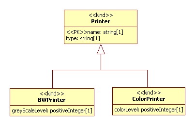
asExtension
Subtype to Supertype
A complexType is created for 'Printer', 'BWPrinter', and
'ColorPrinter' with the later two extending the first.
A complexType is created for 'BWPrinter' and 'ColorPrinter".
Both a group and attributeGroup are created as needed depending
on the encoding of the attributes in the 'Printer' class. These
groups are referenced by 'BWPrinter' and 'ColorPrinter'.
A complexType is created for 'Printer', 'BWPrinter' and
'ColorPrinter' with the first directly including the latter two.
An optional choice group reflects the choice between these two
mutually exclusive subtypes.
A complexType is created for 'Printer'. Both a group and / or
attributeGroup are created as needed for each of 'BWPrinter' and
'ColorPrinter' depending on the encoding of the attributes in
each of them. An optional choice group reflects the choice
between these two mutually exclusive subtypes.
[ISO-TR9007] ISO/TR9007:1987(E) Information processing systems -
Concepts and terminology for the conceptual schema and information base,
1987.
[Nečaský-2006] Nečaský, Martin, Conceptual Modeling for XML: A Survey, Proceedings of the Dateso 2006 Annual International Workshop on DAtabases,
TExts, Specifications and Objects, Desna, Czech Republic, April 26-28,
2006.
[Verelst-2004] Verelst, J. Variability in Conceptual
Modeling, University of Antwerp, 2004.
[1] Surprisingly the claim that these visual languages represent an
implementation, and do not directly model the UoD is controversial in some
communities of practitioners. A well written, and thorough treatment of this
topic in the data modeling community can be found in Simsion-2007
[2] A survey of some of the conceptual modeling proposals that have been made for
XML can be found in Nečaský-2006
[3] As opposed to those aspects of a modeling language that should always be
generally true. Guizzardi explores this in chapter 2 of Guizzardi-2005. An informal description of desirable properties
of a model can be found at
http://www.idiagram.com/ideas/models.html
[4] The phrase reasonable level of specificity is
simply an acknowledgement that no formal modeling language can
capture all of the nuance of a concept necessary for human
understanding. Prose is still essential. Instead the requirement is
that the modeling language at least convey enough information so
that all the people who read [and understand it] find themselves on
the same street, if not in the same house.
[5] Although this is a requirement, it has not yet been proven.
Because of the extensive expertise of the team that worked on this
project in relational database design, it does seem quite likely
that this will work when we get around to creating the necessary
software.
[6] Once again, this has yet to be proven. An initial assessment as to
the feasibility of this is promising. It would potentially require
the adoption of additional constructs defined in the UFO. The rules
(and resulting code) to map it into OWL DL would likely be easier
then the rules / code currently in place to generate an XML schema.
This is due to the very direct mapping between the constructs in the
conceptual modeling language and OWL DL, and to the fact that
relationship encoding in RDF is prescribed, where as in general XML
the variability in how relationships are encoded is considerable.
[7] This requirement is driven by the practical resource constraints
of being able to find people with the correct skill set for creating
conceptual models for information systems.
[8] Construct variability, defined in Verelst-2004,
is the use of different modeling constructs (e.g., attribute vs.
entity) to represent the same real-world concept.
[9] Horizontal and vertical variability is defined in Verelst-2004. Vertical variability is the use of
different levels of generalization / abstraction to conceptualize
the same UoD. Horizontal variability is the use of different
categorizations at the same level of generalization / abstraction.
[10] Ontology is not the sole discipline that can shed light on conceptual
modeling. Epistemology, phenomonology, semiotcs, linguistics, cognitive
psychology, and communication theory are but a few that have something to add,
and are indeed used in Guizzardi's work.
[11] Optionality is fine on whole-part relations, where optional parts are a
perfectly reasonable thing.
[12] It is hoped that the strict definition of what it is to be an attribute,
will reduce the construct variability that is often present in models where
attributes are used to represent both simple properties and
relationships.
[13]In the pre-UML days, people were usually rather vague on what was
aggregation and what was association. Whether vague or not, they were
always inconsistent with everyone else. As a result, many modelers think
that aggregation is important, although for different reasons. So the
UML included aggregation, but with hardly any semantics. (Fowler-2000 , p. 85)
[14] Name changes are typically necessary to accommodate local conventions in
terminology, and local syntactic naming standards. In a conceptual model names
are chosen for clarity, and can be long, and will not necessarily agree with
jargon spoken by a specific community.
[15] The XML Metamodel Interchange (XMI) format was briefly considered as a choice
for the serialization of the model. It does in fact have all of the needed
information. It was not chosen because its structure, optimized to exchange
[complete] models between modeling tools, is not ideal for creating clean XSLT
code for transformation into an XSD. In addition, the benefits of using a
standard tool-neutral serialization of a UML model are partially obviated by the
inconsistent and limited implementation of the standard in some modeling tools.
That said, the use of XMI is something that will be considered the future. An
appropriate XSLT 2.0 function library could be used to hide the complexities of
the XMI format.
[16] An example of such clean-up is the removal of any xsd:group or
xsd:attributeGroup structures that are only referenced once, by
collapsing them within their referent.
[17] Its quite challenging to keep straight all of the orthogonal concerns,
some subset of which much all come together in the final physical design,
but which should be thought about and modeled separately at the conceptual
level. For example, for any given information structure in a PDM, the
following different concerns might need to be addressed in addition to the
real-world object that the information structure is describing. How is
temporal change of that object's properties handled; how is the provenance
of the information (e.g., origin, trustworthiness) recorded; how is system
related metadata (e.g., who created it, when it will be deleted, access
control, versioning) represented, etc.
[18] Sperberg-McQueen touches on the desirability of You
have to say everything twice in Sperberg-McQueen-2008. The longer term goal of
this work is to say things many times, in prose, in the
conceptual modeling language, and in designs for XSD, DDL, and
OWL.
[19] This reverse engineering is necessarily manual. The mapping
between a given implementation back up to a conceptual model is
many to one. This is unlike a mapping between a schema language
and a simple visualization of it, as is typically implemented in
tools today.
[21] The primitive type on which the user defined data type
is a restriction of, is recorded directly as a property
in the modeling tool. If a user defined datatype is a
restriction of another user defined datatype, it is
represented as a generalization relation.
[22] The element names are created by selecting a name
encoding option that combines an attributes name
with its class name.
Nečaský, Martin, Conceptual Modeling for XML: A Survey, Proceedings of the Dateso 2006 Annual International Workshop on DAtabases,
TExts, Specifications and Objects, Desna, Czech Republic, April 26-28,
2006.